
Moon-Bouncing
Relativity: The Wrecking Ball
The Energetic Forum
http://www.energeticforum.com/eric-dollard-official-forum/9727-who-performs-first-longitudinal-moon-bounce-history.html
Who will perform the first longitudinal Moon-Bounce in history?
Eric Dollard Official Forum This forum is dedicated to the work of Eric P. Dollard. His Official homepage is http://ericpdollard.com
See also: http://www.gestaltreality.com/energy-synthesis/eric-dollard/additional-posts-by-e-p-dollard/ for further info on this page
 Forum Posts
#1
Old 11-03-2011, 02:43 PM
lamare’s Avatar
lamare lamare is offline
Gold Member
Join Date: Oct 2008
Posts: 1,212
Who performs the first longitudinal Moon-Bounce in history?
Hi all, I’m sure many of you know about moon-bouncing in amateur radio:
EME (communications) – Wikipedia, the free encyclopedia
Quote:
The use of the Moon as a passive communications satellite was proposed by Mr. W.J. Bray of the British General Post Office in 1940. It was calculated that with the available microwave transmission powers and low noise receivers, it would be possible to beam microwave signals up from Earth and reflect off the Moon. It was thought that at least one voice channel would be possible.
The “moon bounce” technique was developed by the United States Military in the years after World War II, with the first successful reception of echoes off the Moon being carried out at Fort Monmouth, New Jersey on January 10, 1946 by John H. DeWitt as part of Project Diana. The Communication Moon Relay project that followed led to more practical uses, including a teletype link between the naval base at Pearl Harbor, Hawaii and United States Navy headquarters in Washington, DC. In the days before communications satellites, a link free of the vagaries of ionospheric propagation was revolutionary.
Later, the technique was used by non-military commercial users, and the first amateur detection of signals from the Moon took place in 1953.
In my Einstein article I added this:
Tuks DrippingPedia : Ruins 106 Years Einstein Relativity
Quote:
Given that the propagation speed of longitudinal electric waves (which according to the current theory cannot propagate trough a vacuum) is about 1.6 times the speed of light, it would be a very interesting experiment to see whether or not moon bouncing could be achieved practically with longitudinal electric waves. If Tesla is right, we would see an Earth-Moon-Earth roundtrip time of in the order of 1.6 seconds, while normal EM waves would take more than 2.5 seconds. Since the distance between the Earth and the Moon is on average 384,400 km, on average we would have a return path of over 750,000 km, which would take more than 2.5 seconds at the speed of light, which is the speed with which EM waves propagate. However, longitudinal waves could make the round-trip in just 1.6 seconds, a difference of 0.9 seconds!
I mean, explaining away a couple of nanoseconds in the CERN neutrino “anomaly”, all right, they get away with that. But I would really love to see how they would explain away an early arrival of no less than 0.9 seconds…
So, if we were to make a longitudinal transmitter of considerable power (Wikipedia says you need over 100W for EM waves, but the higher the gain of your antenna’s, the less power you need) and we would connect that to a computer (transmitting f.e. audible morse code or something), you could setup a system whereby any (radio amateur) could enter a message trough the Internet to a server, connected to a transmitter which sends the signal to the moon. Now since any decent Internet connection should be able to get the message from the amateurs computer to the transmitter computer well within half a second, any radio amateur that builds a receiver should be able to determine that the signal he himself entered on the computer is being received from the moon well before any EM wave could possibly travel back and forth between the earth and the moon.
That way, it could be experimentally proven that:
a) longitudinal waves exist,
b) they travel at much a faster speed than the speed of light.
This would mean that it could be experimentally proven that the current Maxwell equations are wrong and that therefore the Lorentz transform is rubbish after all and thus Einsteinan relativity can finally be put where it belongs: the trash can.
Since radio amateurs have been using moon-bouncing before, such an experiment using longitudinal waves may be possible without requiring large amounts of funding.
So, I went looking for some information on how to do this in practice, and it seems that all you need to be able to transmit and/or recieve longitudinal waves is spherical antenna:
Monstein, Wesley – Observation of scalar longitudinal electrodynamic waves(2002).pdf
Quote:
Mathematically a spherically symmetric source can generate only scalar waves; so the ball antenna can only generate a Φ-wave, and, thus, only a longitudinal electrodynamic E -wave. The spherically symmetric current density J within the ball, that gives rise to the pulsating surface charge source, is divergenceless, ∇ · J = 0; so ∇ · A = 0 and ∇× A = 0; and no transverse wave can arise. The ball antenna as a receiver detects the net charge induced by the component of the incident E field normal to the front surface; so only longitudinal E-waves can be detected.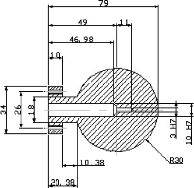
This is the sketch of the aluminium ball antennas from the pdf:
Now if you would mount such antenna’s on a set of ordinary satellite dishes, you could perhaps easily build longitudinal antenna with high gain, as some people do for the transmission of EM WiFi signals:
How-To: Build a WiFi biquad dish antenna — Engadget
TREVOR MARSHALL – Biquad feed for primestar dish
It seems to me that this is not only doable, but also doable within a reasonable hobby-budget.
So, which radio amateur is going to get his name in the history books for performing not only the first longitudinal moon-bounce, but also delivering the final blow to Einstein’s nonsense known as his relativity theory?
__________________
On Space Time And The Fabric Of Nature
Simulating an aether model of EM using OpenFoam?
Who performs the first longitudinal Moon-Bounce in history?
Last edited by lamare; 11-04-2011 at 06:41 PM. Reason: typo, cleaned up link to Monstein&Wesley, typo
Reply With Quote
#2
Old 11-03-2011, 04:39 PM
broli broli is offline
Silver Member
Join Date: Aug 2008
Posts: 530
Nikola Tesla (yeah the dead guy) may have beat you to the punch:
Nikola Tesla “Lost” Manuscript? Not Verified as being authentic or not. Read it for yourself.. | MERLib.org
Read part 2.
__________________
Reply With Quote
#3
Old 11-03-2011, 06:49 PM
boguslaw’s Avatar
boguslaw boguslaw is online now
Gold Member
Join Date: Aug 2007
Posts: 2,321
Wave going inside conductor of spherical shape with the speed of c occur on surface as a shadow of speed (Pi/2)*c Maybe that neutrino distraction is exactly that, surface of earth not counted into computations.
__________________
Reply With Quote
#4
Old 11-03-2011, 07:14 PM
Michael John Nunnerley’s Avatar
Michael John Nunnerley Michael John Nunnerley is offline
Gold Member
Join Date: May 2008
Posts: 1,186
radio waves and OU
Quote:
Originally Posted by broli View Post
Nikola Tesla (yeah the dead guy) may have beat you to the punch:
Nikola Tesla “Lost” Manuscript? Not Verified as being authentic or not. Read it for yourself.. | MERLib.org
Read part 2.
As most may know or not know, I have been a radio ham for most of my life and when I started using HF for long distance communication I was very surprised to be able to use 2.5watts of RF power and speak from England to Australia with the Australian end reading an off scale reading on his RF meter. Now that was not moon bounce “though I have done that”, it was propergation during high sun spot activity and bouncing off the ionospher several times to earth and back again until it reached the reciever in Australia.
Now the question is, was the 2.5 watts of RF increased as it bounced around the earth until it reached the receiver in Australia? It would seam it did as shown by the RF meter used in Australia!!!!! line of sight would not give such a large RF meter reading at maximum distance possible from transmitter to receiver!
Mike
__________________
Reply With Quote
#5
Old 11-03-2011, 08:51 PM
lamare’s Avatar
lamare lamare is offline
Gold Member
Join Date: Oct 2008
Posts: 1,212
Quote:
Originally Posted by boguslaw View Post
Wave going inside conductor of spherical shape with the speed of c occur on surface as a shadow of speed (Pi/2)*c Maybe that neutrino distraction is exactly that, surface of earth not counted into computations.
Dollard wrote about the speed of longitudinal waves propagating at a speed of pi/2 times c:
Tuks DrippingPedia : Transmission Of Electricity
Quote:
The electromagnetic theory, or what was known as the Hertzian wave theory in Tesla’s era, fails to explain certain observations made in practical radio engineering. According to E.M. theory the propagating velocity of electric induction must be the velocity of light. In the practical world of engineering however, the factor π/2, or 1.57 times the velocity of light will appear in wave calculations. Is it not coincidental that Tesla claimed that the effective propagation velocity of his wireless system was π/2 faster than the so-called speed of light?
Also, according to E.M. theory, the propagation of electric induction must be the cross combination of the dielectric induction and the magnetic induction, these two inductions never propagating independently. The work of J.J. Thomson and M. Faraday indicate that these two distinct forms of induction do propagate independently. Wheatstone claimed that the dielectric induction propagated at π/2 times faster than light.
Tuks DrippingPedia : Induction In The Dimension Of Time
Quote:
Lord Kelvin felt that it was possible to establish compressional waves, such as sound waves, thru the luminiferous aether, these waves being a version of Maxwell’s displacement current. This current, often called capacitor current, flows thru electric insulators, and even thru so called empty space. No conductors or electron flux is involved with this current. Kelvin indicated his feelings that these waves must prop*agate faster than the velocity of light. To quote Kelvin’s description of the actions of the induction in the space between the plates of a capacitor fed by an alternator:
Quote:
“Now does any one believe that, if the revolution were made fast enough, the electro-static law of force, pure and simple, would apply to the air at different distances from each plate? Everyone believes that if the process can be conducted fast enough, several million times, or millions of millions times per second, we should have large deviations from the electro-static law in the distribution of electric force through the air in the neighborhood. It seems absolutely certain that such an action as that going on would give rise to electrical waves. Now, it does seem to me probable that these electrical waves are conden*sational waves in the luminiferous aether; and probably it would be that the propagation of these waves would be enormously faster than the propagation of ordinary light waves.”
The velocity of dielectric propagation was experimentally verified by Prof. Wheatstone to be π/2 times faster than the velocity of light. Tesla also states this velocity in his writings on wave propagation.
In view of these scientific discoveries, and the fact that Oliver Heaviside developed a theory of faster than light electrons which was confirmed by Dr. Tesla, it is a wonder how the present notions of electro-magnetism and its limiting velocity as purported by Einstein an his follo*wers have dominated electric theory. It is of particular interest to note that C.P. Steinmetz did not consider Hertzian waves as transmission of energy but as energy loss by the hysteresis of the aether.
Tuks DrippingPedia : Sbarc Lecture
Quote:
As wireless progressed, Tesla established the system where he could transmit [electrical power] longitudinally through the earth at a velocity of 291,000 mi./s. Also he developed a beam tube […]
(Skeptic interrupts) whoa, what was that speed?
291,000 mi./s, Pi over 2 times the velocity of light.
(Skeptic) 186,000 mi./s is C, I think you’re exceeding C, maybe kilometers?
No, it’s Pi over 2 times the velocity of light.
(Chris Carson) he is exceeding c, he’ll go on and explain.
(Skeptic) okay.
There’s a different set of dimensions. The velocity of light simply is an expression of the ratio between energy and mass.
(Skeptic) right, which is a limit.
A limit to what?
(Skeptic) a constant…
It’s a constant. Not a limit.
In the beam, Tesla found that he could transmit direct current energy over incredible distances, and this energy not diverging out of the beam, much tighter, more compact than any laser ever built. In the longitudinal mode through the ground, there were really no losses and the lightbulb would light up at the other end. Marconi, in an attempt to circumvent the Tesla patents, changed the impedance of the system and used the flat top antenna where you would get transverse electromagnetic propagations at 186,000 mi./s and longitudinal magnetic dielectric transmissions at 291,000 mi./s. For those that want to go back through history, Prof. Wheatstone proclaimed that the velocity of electrostatic induction was Pi over 2 times the velocity of light. Those of you that know about electronics and electricity, I’m sure you’ve heard of the Wheatstone bridge. Wheatstone was a very important researcher.
Wikipedia says this on its page on Wheatstone:
Charles Wheatstone – Wikipedia, the free encyclopedia
Quote:
Velocity of electricity
He achieved renown by a great experiment — the measurement of the velocity of electricity in a wire. He cut the wire at the middle, to form a gap which a spark might leap across, and connected its ends to the poles of a Leyden jar filled with electricity. Three sparks were thus produced, one at either end of the wire, and another at the middle. He mounted a tiny mirror on the works of a watch, so that it revolved at a high velocity, and observed the reflections of his three sparks in it. The points of the wire were so arranged that if the sparks were instantaneous, their reflections would appear in one straight line; but the middle one was seen to lag behind the others, because it was an instant later. The electricity had taken a certain time to travel from the ends of the wire to the middle. This time was found by measuring the amount of lag, and comparing it with the known velocity of the mirror. Having got the time, he had only to compare that with the length of half the wire, and he could find the velocity of electricity. His results gave a calculated velocity of 288,000 miles per second, i.e. faster than what we now know to be the speed of light, but were nonetheless an interesting approximation.
It was afterwards found that the velocity of an electric field travelling in a cable depends on the nature of the conductor, its resistance, and its electro-static capacity. Michael Faraday showed, for example, that its velocity in a submarine wire, coated with insulator and surrounded with water, is only 144,000 miles per second (232,000 km/s), or still less. Wheatstone’s device of the revolving mirror was afterwards employed by Léon Foucault and Hippolyte Fizeau to measure the velocity of light.
I found a pdf with his “An Account of some Experiments to measure the Velocity of Electricity andthe Duration of Electric Light.” and made an OCR version:
http://www.tuks.nl/pdf/Reference_Mat…ic%20Light.pdf
Quote:
The deviation of half a degree between the two extreme sparks, the wire being, as above stated, half a mile in length, would indicate a velocity of 576,000 miles in a second. This estimated velocity is on the supposition that the electricity passes from one end of the wire to the other: if, however, the two fluids in one theory, or the disturbances of equilibrium in the other, travel simultaneously from the two ends of the wire, the two external sparks will keep their relative positions, the middle one will be alone deflected, and the velocity measured will be only half that in the former case, viz. 288,000 miles in a second.
So far, I have not be able to find a theoretical explanation that gives us this pi/2.
__________________
On Space Time And The Fabric Of Nature
Simulating an aether model of EM using OpenFoam?
Who performs the first longitudinal Moon-Bounce in history?
Reply With Quote
#6
Old 11-03-2011, 10:17 PM
Aether’s Avatar
Aether Aether is offline
Member
Join Date: Aug 2010
Posts: 36
Thanks for that Wheatstone document Lamare, I keep reading all over the internet that Wheatstone’s results were due to a calibration error in his tests, but I can never find an explanation as to what the specific error was, is anyone able to substantiate this claim?
__________________
Reply With Quote
#7
Old 11-03-2011, 10:59 PM
lamare’s Avatar
lamare lamare is offline
Gold Member
Join Date: Oct 2008
Posts: 1,212
Finally found something of an answer in the right direction:
Why do transverse waves travel faster than longitudinal waves? – Yahoo! Answers
Quote:
In solids, p-wave (longitudinal) speed is compressive strength [Oops! I mean modulus] divided by density of the medium; s-wave (transverse) speed is sheer strength [Oops! I mean modulus] divided by density. Transverse waves are always slower than longitudinal waves in the same medium because sheer strength is always less than compressive strength. Earthquake waves, for example: The p-waves are many times faster than the s-waves. [Modulus us like a spring constant; it’s the ratio of stress to strain.]
A gas has no sheer strength, so it does not provide a medium for transverse waves. So there are no transverse waves in air that can be compared to sound waves.
And some formulas:
Seimic Waves and Earth’s Interior
Quote:
P-waves are the first waves to arrive on a complete record of ground shaking because they travel the fastest (their name derives from this fact – P is an abbreviation for primary, first wave to arrive). They typically travel at speeds between ~1 and ~14 km/sec. The slower values corresponds to a P-wave traveling in water, the higher number represents the P-wave speed near the base of Earth’s mantle.
The velocity of a wave depends on the elastic properties and density of a material. If we let k represent the bulk modulus of a material, m the shear-modulus, and r the density, then the P-wave velocity, which we represent by a, is defined by:
P Velocity
A modulus is a measure of how easy or difficulty it is to deforms a material. For example, the bulk modulus is a measure of how a material changes volume when pressure is applied and is a characteristic of a material. For example, foam rubber has a lower bulk modulus than steel.
P-waves are sound waves, it’s just that in seismology we are interested in frequencies that are lower than humans’ range of hearing (the speed of sound in air is about 0.3 km/sec). The vibration caused by P waves is a volume change, alternating from compression to expansion in the direction that the wave is traveling. P-waves travel through all types of media – solid, liquid, or gas.
Quote:
Secondary , or S waves, travel slower than P waves and are also called “shear” waves because they don’t change the volume of the material through which they propagate, they shear it. S-waves are transverse waves because they vibrate the ground in a the direction “transverse”, or perpendicular, to the direction that the wave is traveling.
Tranverse Wave Motion
As a transverse wave passes the ground perpendicular to the direction that the wave is propagating. S-waves are transverse waves.
The S-wave speed, call it b, depends on the shear modulus and the density
S-velocity
Even though they are slower than P-waves, the S-waves move quickly. Typical S-wave propagation speeds are on the order of 1 to 8 km/sec. The lower value corresponds to the wave speed in loose, unconsolidated sediment, the higher value is near the base of Earth’s mantle.
An important distinguishing characteristic of an S-wave is its inability to propagate through a fluid or a gas because a fluids and gasses cannot transmit a shear stress and S-waves are waves that shear the material.
__________________
On Space Time And The Fabric Of Nature
Simulating an aether model of EM using OpenFoam?
Who performs the first longitudinal Moon-Bounce in history?
Last edited by lamare; 11-03-2011 at 11:03 PM.
Reply With Quote
#8
Old 11-03-2011, 11:23 PM
broli broli is offline
Silver Member
Join Date: Aug 2008
Posts: 530
I think the medium is indeed more important. You can easily send longitudinal electric waves, it happens all the time in wires and whatnot but experiments show those don’t exceed the speed of light, in fact they slow it down. So the aether might show something different if you can manage to send a true longitudinal electric wave. Meyl also showed this. I’m also interested in the following question; Is this new speed a new limit then?
Instantaneous transfer would be the ultimate goal and this has even been demonstrated with the concept of global scaling formulated by Hartmut Müller.
__________________
Last edited by broli; 11-03-2011 at 11:25 PM.
Reply With Quote
#9
Old 11-04-2011, 09:50 AM
lamare’s Avatar
lamare lamare is offline
Gold Member
Join Date: Oct 2008
Posts: 1,212
NASA’s Advanced Energetics for Aeronautical Applications: Volume II also has a piece on longitudinal waves, referring a.o. to Eric Dollard (BSRF):
Click to access Reference_Mat…20VOL%20II.pdf
page 61:
Quote:
The BSRF researchers claimed that they have demonstrated that the wave propagation velocities of transverse waves and longitudinal waves are significantly different, even when they are produced by the same signal source.
The wave velocity of transverse waves was determined by measuring the frequency for which low-power radio waves directly coupled to the end of a conductor of known length produced a resonance condition that resulted in a maximum voltage measured at the “far” (nonsource) end of the conductor. Wave velocity was calculated as (resonant) frequency times wave length, which was equal to frequency times conductor length times four. (The factor of four is included because reflected energy and input energy result in a maximum output when the conductor length is one-quarter of the full [electric] wave length.) The wave velocity of longitudinal waves was determined in a very similar manner; however, the radio waves were capacitively (i.e., not directly) coupled to one end of a conductor equal in length to the conductor used for the transverse wave velocity measurement. As was done for transverse waves, wave velocity was calculated as (resonant) frequency times conductor length times four.
The results of these determinations were as follows:
– transverse wave velocity = 2.44 x 10⁸ m/s = 0.81 x c; and
– longitudinal wave velocity = 3.74 x 10⁸ m/s = 1.25 x c.
The velocity of transverse waves in “free space” (i.e., not confined to a conductor or other physical material) has been measured to be 3.00 x 10⁸ m/s, and this value is commonly referred to as “the velocity of light, c” (Ref. 25).
When we divide these velocities we get 1.25 / 0.81 = 1.54, very close to 1.57 (pi/2).
In other words: these measurements by Eric Dollard a.o. confirm that with a conductor as a medium, in which the speed of light equals 0.81 x c, the longitudinal waves propagate a factor pi/2 faster than the transverse waves.
Update:
Fort those not so familiar with Eric Dollard’s work, there are some video’s available with his experiments. It appears NASA refers to these video’s…
At Vimeo:
Tesla’s Longitudinal Electricity – Eric Dollard, Peter Lindemann & Tom Brown
Transverse & Longitudinal Electric Waves – Eric Dollard And Thomas Joseph Brown
At YouTube:
Eric Dollard Peter Lindemann Tesla’s Longitudinal Electricity
Eric Dollard Tesla Longitudinal wave Energy SBARC Ham Radio with Chris Carson
(Partial) transcript of this one: Tuks DrippingPedia : Sbarc Lecture
__________________
On Space Time And The Fabric Of Nature
Simulating an aether model of EM using OpenFoam?
Who performs the first longitudinal Moon-Bounce in history?
Last edited by lamare; 11-04-2011 at 06:35 PM. Reason: Added vids
Reply With Quote
#10
Old 11-04-2011, 09:23 PM
lamare’s Avatar
lamare lamare is offline
Gold Member
Join Date: Oct 2008
Posts: 1,212
Size of sphere
I have been thinking a bit about how big the sphere should be. As with Herzian antenna, I think you would want a sphere with a 1/4 lambda radius.
Given that the propagation speed of longitudinal waves is pi/2 times the propagation speed of a normal transversal wave trough the medium at hand, you would have to make the radius pi/2 times the quarter wave length as you would normally calculate for a 1/4 lambda antenna for EM operation.
So, to calculate the ideal radius, you take the desired frequency and divide that by 1.57 (pi/2) to get the EM frequency with the same wave length. Then you can apply normal calculation.
And if you’re working with a 1/4 lambda sphere antenna, the size of the sphere is such that it matters how it is feeded. The feed should be at the centre.
If you do not feed it at the centre, you would have to take a much smaller sphere, which would mean that you have to use much higher voltages to get the same amount of radiation. See for example:
longitudinal waves
Quote:
Technology of Tesla require high potential source (up to millions Volts) that produce high frequency oscillations. Terminal that create the longitudinal wave is the spherical metal surface (sphere capacitor).
And remember that Tesla worked in the kHz bands, which does not seem such a good idea to me if we want to aim for a succesfull moon-bounce while having to do without a power plant in our back yard….
Also do not be fooled by the numerous pages about Tesla’s Wireless Transmitter, like for example the kits and such sold by Prof. Meyl:
ETZS-Shop – Hardware
http://www.k-meyl.de/go/Primaerliter…alar-Waves.pdf
THIS IS NOT A SCALAR WAVE TRANSMITTER!!
It is a small-scale replication of Tesla’s Magnyfing Transmitter, which is NOT supposed to radiate at all!
It is designed to PREVENT radiation!
See my earlier post:
Quote:
Originally Posted by lamare View Post
<snip>
Tesla illustrated this himself in an article “THE TRANSMISSION OF ELECTRICAL ENERGY WITHOUT WIRES” on March 5, 1904, which you can find at:
Transmission of Electrical Energy Without Wires
He used the following illustration to show the difference between electromagnetic radiation (either “Herzian” or longitudinal, btw) and his system:
The text in the upper part of the picture reads:
Quote:
Electromagnetic Hertz waves radiated horiontally from vertical conductor, slightly affected by conducting Earth surface.
ENERGY UNRECOVERABLE
Now why is this so important? Because no matter what kind of waves are transmitted from the vertical conductor, with or without a sphere on top, the energy radiates away in all directions and is therefore lost for all but a very small fraction!
This same picture is also printed in Eric Dollard’s book, with the following comment:
Tuks DrippingPedia : Theory Of Wireless Power
Quote:
It can therefore be seen that while the transmission of transverse waves involves the spraying of energy, with its consequent square law diminishment of energy density, and no hope of retrieving the unused energy, the Tesla system involves the direct connection of transmitter and receiver, via the pulsating lines of electric induction. Therefore, the transmitter and receiver are rendered as one apparatus.
<snip>
Now finally, back to your questions. First of all, yes, there are longitudinal waves being transmitted/exchanged between the transmitter and reciever balls. The point is that these radiate in all directions, no matter whether they are electromagnetic (Herzian) waves or Tesla’s longitudinal waves. Both kind of waves diminish very rapidly when not quided such as to form a standing wave, because the energy is sprayed into space in both cases!!!!
In Tesla’s own words:
Nikola Tesla On His Work With Alternating Currents — Chapter IV
Quote:
I prefer to reduce those waves in quantity and pass a current into the earth, because electromagnetic wave energy is not recoverable while that [earth] current is entirely recoverable, being the energy stored in an elastic system.
So, to sum this up:
Yes, longitudinal waves as well as transversal waves are transmitted by your sphere/coil arangement. And yes, you can detect them at some distance and use them to transfer energy over a small distance. The point is that this kind of energy radiaton should be avoided as much as possible, because all energy radiated into space is wasted can cannot be recovered. And the energy gain that Tesla found, and which is why he called his invention the “Magnifying Transmitter”, is to be found in the higher order resonance standing wave in/along the “ground” connection between transmitter and receiver.
So, the critical component in a magnifying system is the “ground” connection between transmitter and receiver, which should be in higher order resonance and non-radiating. And that is the essential difference between the transmission of energy “trough the air” and Tesla’s system.
Btw, the term scalar wave is an oxymoron. Dollard:
Tuks DrippingPedia : Energetic Form Posts
Quote:
I had a young student from Korea visit me a few years back. He had no problem understanding the basic concept of producing an energy synthesizing apparatus, because his mind was uncontaminated by all of the Bedini/Bearden falsehoods. The term Scalar Wave is an oxymoron, as scalar is part of the propagation constant that is NOT A WAVE! (Idiots!)
[…]
The disinformers have convinced you that this whole quantity (RB + XB) is scalar, RG is the only scalar component. It is DC and has NO FREQUENCY, no WAVELENGTH and thus NO WAVE!
SCALER = NO WAVE
GET IT???
So, let’s call the beast by it’s proper name from now on: Longitudinal Dielectric Wave. No Magnetic component! No Scalar. It’s a wave…
So, now we know what we are talking about, it is clear that the actual transmission of HF longitudinal waves using low-voltages is basically unexplored territory. All the TMT replications currently out there are completely different beasts, because the spheres they are using are not designed as antenna.
So, what we are facing is most of all the question of how to design our transmitter sphere antenna. It should have a radius of 1/4 lambda and should be fed from the centre of the sphere. With such a configuration, the antenna hopefully behaves pretty much like a normal 1/4 lambda antenna from the point of view of the transmitter. And that is important, because we need to have the proper impedance in order to get the energy from our transmitter into our antenna.
Yes, you can use much smaller spheres and use the big hammer method with high voltages as Tesla did. If you want to do that: good luck.
But if you want to get something working with a normal transmitter: go for a 1/4 lambda sphere.
Now let’s take a look at what Monstein and Wesley did:
Monstein, Wesley – Observation of scalar longitudinal electrodynamic waves(2002).pdf
They used a frequency of 433.59 MHz, with an equivalent EM frequency of 276 MHz. When we feed that in a wavelength calculator (Frequency Wavelength Calculator ), we get a wavelength of about 1.1 m or 1/4 lambda of 27 cm, while they used a sphere with a radius of 30 mm, which would be about 10% more than 1/4 lambda. And apparantly that works pretty well, including the way they feed it, which is at the centre indeed.
How nice. The theory matches the practical implementation for a change.
__________________
On Space Time And The Fabric Of Nature
Simulating an aether model of EM using OpenFoam?
Who performs the first longitudinal Moon-Bounce in history?
Last edited by lamare; 11-05-2011 at 10:39 PM. Reason: typo, added link
Reply With Quote
#11
Old 11-05-2011, 04:02 PM
lamare’s Avatar
lamare lamare is offline
Gold Member
Join Date: Oct 2008
Posts: 1,212
After a discussion on a Dutch radio amateur forum, which hopefully leads to contacts with some people that may actually be able to pull this off, I concluded that a sphere antenna actually needs to have a n * 1/2 lambda radius.
The Dutch discussion is here:
Zendamateur.COM – Toon onderwerp – Wie voert de eerste longitudinale moon-bounce uit??
It may also be possible to use other shapes of antenna. The essential difference between transversal and longitudinal modes is this:
a) a difference between propagation speed with a factor pi/2 regardless of the medium;
b) “open” versus “closed” feedline.
One end of the antenna, wether a sphere or a straight wire, is always open. That’s where you per definition get a voltage node. At the feed point, you get either a voltage or a current node, depending on wether or not the feed point is able to “float” freely with regards to it’s potential.
Normally, the feed is connected to a more or less fixed potential, so you get a current node at your feed. Since Eric Dollard used capacitive coupling in his longitudinal demonstration, I concluded that you need to have a voltage node at your feed, which you can achieve by capacitively coupling your transmitter to the feed point.
The interesting thing is that because of the factor pi/2 (1.57) the resonance frequencies of longitudinal vs. transversal modes are that different that your eventual configuration gets a clear preference for one of these modes at the desired frequency. In other words: you can suppress the transversal mode substantially with proper design.
So, in order to make a longitudinal transmitter antenna, you need to make an n * 1/2 lambda antenna *and* you have to make sure that *both* ends of your antenna are “open” with respect to the applied potential, so hardly as little current as possible flows between your transmitter and your antenna, which results in the magnetic (transversal) components of your wave being supressed to a substantial degree.
__________________
On Space Time And The Fabric Of Nature
Simulating an aether model of EM using OpenFoam?
Who performs the first longitudinal Moon-Bounce in history?
Reply With Quote
Sponsored Links
Bedini RPX Sideband Generator
BEDINI RPX
SIDEBAND GENERATOR
FREE BOOK OR VIDEO OFFER
INCLUDED WITH ANY PURCHASE
Available here: Bedini RPX Sideband Generator
#12
Old 11-05-2011, 10:01 PM
lamare’s Avatar
lamare lamare is offline
Gold Member
Join Date: Oct 2008
Posts: 1,212
Posted this on the jk_wireless Yahoo group:
Yahoo! Groups
Quote:
I have been theorizing on how to build a system for the transmission of longitudinal waves, after I found this article wherein a succesfull practical proof of concept is described:
http://bit.ly/sKQUok
Since it was reported by Dollard that the propagation speed of longitudinal waves is a factor pi/2 (1.57) larger than the propagation speed of transversal waves, I figured a demonstration of longitudinal moon bouncing would be THE final chapter for Einstein’s relativity nonsense, so I started a thread at the EF to see how far we can come with that:
http://www.energeticforum.com/renewa…e-history.html
Most important conclusion so far is that your sphere has to have an n * 1/4 lambda radius in order for it to resonate like a dipole antenna, since with a n * 1/4 lambda radius, you basically have an infinite array of 1/2 wave dipoles….
Now if you want to calculate the wavelength for the frequency you are designing your transmitter for, you can simply calculate the corresponding transversal frequency by dividing your longitudinal frequency by pi/2 (1.57). I calculated that for the values reported in the paper:
http://www.energeticforum.com/renewa…tml#post165383
“They used a frequency of 433.59 MHz, with an equivalent EM frequency of 276 MHz. When we feed that in a wavelength calculator ( Frequency Wavelength Calculator ), we get a wavelength of about 1.1 m or 1/4 lambda of 27 cm, while they used a sphere with a radius of 30 mm, which would be about 10% more than 1/4 lambda.”
And apparantly that works pretty well. Interesting detail is that they feed their sphere from the centre, where you have a current node, just as what you have with a normal 1/4 lambda dipole, so you can drive it with a normal transmitter. (oops, that should have been: “a normal 1/2 lambda dipole” or “a normal 1/4 lambda wire antenna”)
If you drive it from the outside, you drive it at a voltage node, which means you drive it with high voltage, low current. Dollard used capacitive coupling in his longitudinal experiment, so that is probaly the way to go if you want to feed your sphere at a point at the outside. It may be a good idea to use a trimmer cap between your coil and your sphere, so you can tune the whole setup.
I realize this gets a bit confusing. What should it be now, n * 1/2 lambda or n * 1/4 lambda??
All right. Now the outside of your sphere is per definition a voltage node. You get these every 1/2 lambda.
If you want to drive your sphere from a normal transmitter, which is designed to feed a normal dipole or 1/4 lambda antenna at a current node, you need to feed your sphere from the centre and it needs to have a radius of n * 1/4 lambda in order to get your current node at the centre in order to keep your transmitter happy.
If you want to drive your sphere from a transmitter capable of driving a dipole at a voltage node (basically: high voltage, low current), you can either use a sphere with a radius of n * 1/4 lamda and drive it from the outside, or you can take a sphere with a radius of n * 1/2 lambda and drive it from the centre.
At this moment it still has to be determined how to drive an antenna at a voltage node exactly.
Eric Dollard’s experiments suggests that capacitive coupling to a normal transmitter may work. A transmitter like Tesla’s TMT probably also works very well, because it’s coil is in a self-resonance mode and normally you use the already “open” side of the coil to drive your sphere. So, if you match the size of your sphere to the oscillation frequency of your TMT when oscillating without any capacitive load at the top, you’re probably O.K.
__________________
On Space Time And The Fabric Of Nature
Simulating an aether model of EM using OpenFoam?
Who performs the first longitudinal Moon-Bounce in history?
Last edited by lamare; 11-05-2011 at 10:32 PM. Reason: oops
Reply With Quote
#13
Old 11-05-2011, 10:44 PM
broli broli is offline
Silver Member
Join Date: Aug 2008
Posts: 530
In that forum someone made an interesting remark, antennas we know radiate or at least should radiate a small, none existent according to maxwell equations, portion longitudinally. This alone is interesting to know and has been mentioned in distinti’s “new electromagnetism theory”.
http://www.distinti.com/docs/apoce.pdf
page 19
I believe there’s a more in depth derivation in some other pdf.
Also why are you worrying about standing waves on the surface of the sphere. What are the frequency ranges you had in mind? If the sphere is small and frequency has meter long wave lengths then it should be a none issue no? Even if you had a huge sphere and high frequency the standing waves on the surface would or should still emit longitudinal waves. Just like a standard antenna emits transverse waves while its length is multiple times the length of the underlying wave.
__________________
Last edited by broli; 11-05-2011 at 10:49 PM.
Reply With Quote
#14
Old 11-05-2011, 10:51 PM
lamare’s Avatar
lamare lamare is offline
Gold Member
Join Date: Oct 2008
Posts: 1,212
Quote:
Originally Posted by broli View Post
Also why are you worrying about standing waves on the surface of the sphere. What are the frequency ranges you had in mind? If the sphere is small and frequency has meter long wave lengths then it should be a none issue no? Even if you had a huge sphere and high frequency the standing waves on the surface would or should still emit longitudinal waves.
Jus try getting low frequency sounds, like a 100 Hz sine wave, from a loudspeaker designed for high frequencies (tweeter) or just any speaker with a very small cone and you know what I mean….
For the moon-bounce project, we need high gain antenna’s and considerable power, so we need to use sattellite dishes as antenna, fed with a sphere. Since readily available dishes have a diameter of in the order of 1 to may be 5m, I am aiming for high frequencies, at least 500 MHz or so.
__________________
On Space Time And The Fabric Of Nature
Simulating an aether model of EM using OpenFoam?
Who performs the first longitudinal Moon-Bounce in history?
Last edited by lamare; 11-05-2011 at 10:55 PM.
Reply With Quote
#15
Old 11-05-2011, 11:18 PM
broli broli is offline
Silver Member
Join Date: Aug 2008
Posts: 530
I’m not knowledgeable in that field.
But what would the difference be between one large surface and many small individual patches covered over a large surface. The boundaries of these small patches do not connect but all are connected to the center of the sphere. Wouldn’t that eliminate the standing wave issue on the sphere?
__________________
Reply With Quote
#16
Old 11-06-2011, 01:28 AM
KurtNalty KurtNalty is offline
Junior Member
Join Date: Oct 2011
Posts: 3
Greetings,
The problem with moonbounce is validating the actual path taken by
the signal. You could imagine ionosphere reflections, intermediate
ionized gas clouds, repeater satellites, Dark Knight repeaters, and
plain old fraud invalidating the exercise.
For what it is worth, AstroEngineer.wordpress.com claims that
Mars rovers (Spirit, etc) are equipped with working superluminal
transmitters. (Checkout the gnomon on the color calibrator
as a candidate for the spherical transmitter.) His claim is that
timestamped data at JPL documents pre-arrival of the data stream
from the superluminal path, as compared to the conventional path.
I think the more convincing prospect for demonstrating superluminal
longitudinal waves is to redo Wheatstone’s demonstration.
__________________
Reply With Quote
#17
Old 11-06-2011, 05:47 PM
lamare’s Avatar
lamare lamare is offline
Gold Member
Join Date: Oct 2008
Posts: 1,212
Quote:
Originally Posted by broli View Post
I’m not knowledgeable in that field.
But what would the difference be between one large surface and many small individual patches covered over a large surface. The boundaries of these small patches do not connect but all are connected to the center of the sphere. Wouldn’t that eliminate the standing wave issue on the sphere?
As far as I can tell, there is no problem once you get a standing wave in your sphere. The idea of using a sphere with a normal transmitter comes from the paper I posted earlier:
Quote:
A spherical surface with a uniform periodic changing net charge q is equivalent to a pulsating point charge density.
[…]
The ball antenna source. –
The geometry of the spherical antenna is indicated in fig. 1. A 433.59 MHz signal is fed into the inside of the metal sphere through a coaxial cable, where the outside grounded conductor acts as a shield. The result is an oscillating uniform spherical charge density that is the source of the radiating longitudinal electric E field. Mathematically a spherically symmetric source can generate only scalar waves; so the ball antenna can only generate a Φ-wave, and, thus, only a longitudinal electrodynamic E-wave. The spherically symmetric current density J within the ball, that gives rise to the pulsating surface charge source, is divergenceless, ∇ · J = 0; so ∇ · A = 0 and ∇ × A = 0; and no transverse wave can arise. The ball antenna as a receiver detects the net charge induced by the component of the incident E field normal to the front surface; so only longitudinal E-waves can be detected. An absorbing screen can be introduced to determine the direction of the incident longitudinal wave. Stray transverse fields generated by leads and neighboring objects play only a minor role.
So, when you feed your sphere from the centre, no matter what, the waves always end up with the same phase at the outside. So, you can work with a small sphere when feeding from the centre without any standing wave problems. When fed from the centre, the problems are mostly related to how much power you can effectively radiate with such an antenna.
When not fed from the centre, it depends on how small your sphere is compared to the wavelenghts used wether or not you get too much unwanted phase differences across the surface of your sphere. If it is small enough, you won’t have a problem with that respect, but you won’t be able to radiate much power either. And a small sphere fed from the center also won’t radiate much power.
Now normally an antenna is designed to resonate in order to get the largest possible radiation. So, I figured: the sphere must also resonate if you want to be able to transmit power effectively. And it turned out that the sphere the guys in the paper used had a radius of about 1/4 lambda.
But feeding a sphere from the centre is very complicated. How do you fix a feedline to the centre of a shpere?
Now when the sphere is designed to resonate at the frequency you desire, you will get a standing wave pattern such that the waves at the surface of your ball are always in phase because of the geometry of the sphere. And then and only then you can feed your sphere from the outside without any problem as far as I can tell, while still being able to radiate the optimum amount of power.
So, from a practical point of view it is much easier to do it like that…
__________________
On Space Time And The Fabric Of Nature
Simulating an aether model of EM using OpenFoam?
Who performs the first longitudinal Moon-Bounce in history?
Last edited by lamare; 11-06-2011 at 06:37 PM. Reason: expanded quote
Reply With Quote
#18
Old 11-06-2011, 07:21 PM
Kokomoj0’s Avatar
Kokomoj0 Kokomoj0 is offline
Senior Member
Join Date: Jul 2011
Posts: 390
Quote:
Originally Posted by KurtNalty View Post
I think the more convincing prospect for demonstrating superluminal
longitudinal waves is to redo Wheatstone’s demonstration.
Yes that is a great idea, with todays equipment, as you said, so it reduces their ability as much as possible to speciously counter argue the matter, as there most likely will be interests that would prefer it is never known that will grab for any straw they can to derail the experiment.
__________________
Reply With Quote
#19
Old 11-06-2011, 07:42 PM
Kokomoj0’s Avatar
Kokomoj0 Kokomoj0 is offline
Senior Member
Join Date: Jul 2011
Posts: 390
@lamare
doesnt the sphere become part of the whole system, which is to say, the best power transfer through the system that could be hoped for would be an exact impedance match between the coil capacitor and the environment at the system level operating frequency? It appears it would be dependent on the physical dimensions of the sphere as you talked about and all external factors, height, nearby objects etc etc? either way it would also need the transmitter to properly load up as well. I am having difficulty imagining how someone can get all these factors knowing what we know about wire mass, length, size etc into a best compromise situation as a system.
If you wanted to feed the center what about putting a small solid core ball on the end of the coax center and insulator from the braid and the coax mounted so the ball is in the center of the sphere?
Oddly enough my now 90 year old uncle used to put a small hollow ball over the tip of all his radio antenna’s including these 900 mhz phones and to my surprize the reception was noticeably better!
__________________
Last edited by Kokomoj0; 11-06-2011 at 08:36 PM.
Reply With Quote
#20
Old 11-06-2011, 08:13 PM
Kokomoj0’s Avatar
Kokomoj0 Kokomoj0 is offline
Senior Member
Join Date: Jul 2011
Posts: 390
Quote:
Originally Posted by lamare View Post
Jus try getting low frequency sounds, like a 100 Hz sine wave, from a loudspeaker designed for high frequencies (tweeter) or just any speaker with a very small cone and you know what I mean….
For the moon-bounce project, we need high gain antenna’s and considerable power, so we need to use sattellite dishes as antenna, fed with a sphere. Since readily available dishes have a diameter of in the order of 1 to may be 5m, I am aiming for high frequencies, at least 500 MHz or so.
coils and design at that frequency get really hairy.
Interestingly I am planning at some point in building a transmitter and that was the frequency of my first choice but am rethinking it due to the added complexities. For what you are trying to do I dont think you have that luxury. Lots of people still have those old 9ft sat dishes in their yards that might be a consideration.
__________________
Reply With Quote
#21
Old 11-06-2011, 08:35 PM
Kokomoj0’s Avatar
Kokomoj0 Kokomoj0 is offline
Senior Member
Join Date: Jul 2011
Posts: 390
Quote:
Originally Posted by lamare View Post
Posted this on the jk_wireless Yahoo group:
Yahoo! Groups
I realize this gets a bit confusing. What should it be now, n * 1/2 lambda or n * 1/4 lambda??
All right. Now the outside of your sphere is per definition a voltage node. You get these every 1/2 lambda.
If you want to drive your sphere from a normal transmitter, which is designed to feed a normal dipole or 1/4 lambda antenna at a current node, you need to feed your sphere from the centre and it needs to have a radius of n * 1/4 lambda in order to get your current node at the centre in order to keep your transmitter happy.
If you want to drive your sphere from a transmitter capable of driving a dipole at a voltage node (basically: high voltage, low current), you can either use a sphere with a radius of n * 1/4 lamda and drive it from the outside, or you can take a sphere with a radius of n * 1/2 lambda and drive it from the centre.
At this moment it still has to be determined how to drive an antenna at a voltage node exactly.
Eric Dollard’s experiments suggests that capacitive coupling to a normal transmitter may work. A transmitter like Tesla’s TMT probably also works very well, because it’s coil is in a self-resonance mode and normally you use the already “open” side of the coil to drive your sphere. So, if you match the size of your sphere to the oscillation frequency of your TMT when oscillating without any capacitive load at the top, you’re probably O.K.
Its too bad Eric did not elaborate on that. He did say he was able to tune up with good swr into the ground in that conference video I believe.
In this case wouldnt you simply impedance match your transmitter to operate into the primary with enough tuning capability to adjust for variations reflected from the tower to maintain a decent swr?
I presume your amp would be electrically isolated and driving the primary coil into the ground no?
Then in a pinch couldnt you adjust your voltage or current mode by a length of coax between the sphere and the top of the coil?
__________________
Reply With Quote
Sponsored Links
Bedini RPX Sideband Generator
BEDINI RPX
SIDEBAND GENERATOR
FREE BOOK OR VIDEO OFFER
INCLUDED WITH ANY PURCHASE
Available here: Bedini RPX Sideband Generator
#22
Old 11-06-2011, 09:23 PM
lamare’s Avatar
lamare lamare is offline
Gold Member
Join Date: Oct 2008
Posts: 1,212
Good news!
If we manage to buld a proper transmitter, we can make use of this 25 meter dish for an experiment:
Dwingeloo Radio Observatory – Wikipedia, the free encyclopedia
The guy who responded to my mail is involved with the restoration of this dish and he said they could mount a feed at “their dish” and “aim a shot”.
WOW!
__________________
On Space Time And The Fabric Of Nature
Simulating an aether model of EM using OpenFoam?
Who performs the first longitudinal Moon-Bounce in history?
Last edited by lamare; 10-31-2013 at 07:52 PM. Reason: uptated url for image.
Reply With Quote
#23
Old 11-07-2011, 09:52 AM
lamare’s Avatar
lamare lamare is offline
Gold Member
Join Date: Oct 2008
Posts: 1,212
The lamare longitudinal dipole antenna (and/or dish feed)…
Yesterday evening, I have been thinking about how to design a longitudinal antenna for use with a normal transmitter. The design used in the Swiss proof-of-concept was fed from the centre, but the coax mantle was floating, which is not such a good idea. This kept bothering me and after some deep thinking, I suddenly got an idea. The lamare longitudinal dipole:
The idea is to make a whip antenna of 1 1/4 lambda, where at the tip of the whip we mount a sphere with a radius of 1/4 lambda. Concentric to that one, we mount a hollow sphere with a radius of 3/4 lambda.
So, in between the spheres you have 1/2 lambda, so both are at a voltage node with a phase difference of 180 degrees.
The outer sphere acts as a reflective shield. I have drawn this one as a half sphere, but of course you can match the opening in the outer sphere to the angle of your dish, and you get some gain as a result.
Since a normal transmitter is designed to couple into a current node, we attach a feedpipe (or how do you call this?) of 1/4 lambda to the outer sphere, which is connected to ground at the feed point.
The inner sphere is connected to the same feed point by means of a 3/4 lambda whip.
The interesting thing is that because of the difference in propagation speed of a factor pi/2, your transversal resonance frequencies are also a factor pi/2 away from the frequency for which we design our longitudinal dipole, which causes a nice suppression of all the transversal junk we don’t want in this case….
Attached Images
File Type: jpg Lamare_Longitudinal_dipole.JPG (43.1 KB, 2 views)
__________________
On Space Time And The Fabric Of Nature
Simulating an aether model of EM using OpenFoam?
Who performs the first longitudinal Moon-Bounce in history?
Reply With Quote
#24
Old 11-07-2011, 05:03 PM
Kokomoj0’s Avatar
Kokomoj0 Kokomoj0 is offline
Senior Member
Join Date: Jul 2011
Posts: 390
in his work on the transmission of electricity, Dollard makes the distinction between dielectric and and magnetic induction but in this paper did not go to the elements of exactly how it works.
Quote:
The electromagnetic theory, or what was known as the Hertzian wave theory in Tesla’s era, fails to explain certain observations made in practical radio engineering. According to E.M. theory the propagating velocity of electric induction must be the velocity of light. In the practical world of engineering however, the factor π/2, or 1.57 times the velocity of light will appear in wave calculations. Is it not coincidental that Tesla claimed that the effective propagation velocity of his wireless system was π/2 faster than the so-called speed of light?
Also, according to E.M. theory, the propagation of electric induction must be the cross combination of the dielectric induction and the magnetic induction, these two inductions never propagating independently. The work of J.J. Thomson and M. Faraday indicate that these two distinct forms of induction do propagate independently. Wheatstone claimed that the dielectric induction propagated at π/2 times faster than light.
Does anyone have any further information of the exact process that takes place that creates the pi/2 c condition?
__________________
Reply With Quote
#25
Old 11-07-2011, 05:18 PM
lamare’s Avatar
lamare lamare is offline
Gold Member
Join Date: Oct 2008
Posts: 1,212
Quote:
Originally Posted by Kokomoj0 View Post
in his work on the transmission of electricity, Dollard makes the distinction between dielectric and and magnetic induction but in this paper did not go to the elements of exactly how it works.
Does anyone have any further information of the exact process that takes place that creates the pi/2 c condition?
In essence, it’s a matter of rotational movement of the ether in the case of the magnetic component versus straight movement in the case of the dielectric component.
The magnetic component travels a netto path of half a circle, pi * r, while the dielectric component travels straight trough the centre of the circle, 2 * r. The division of these renders pi/2. In other words: the path the magnetic component has to travel is pi/2 times as long as the path the dielectric component has to travel. The magnetic component takes a detour, while the dielectric component does not….
__________________
On Space Time And The Fabric Of Nature
Simulating an aether model of EM using OpenFoam?
Who performs the first longitudinal Moon-Bounce in history?
Last edited by lamare; 11-07-2011 at 06:22 PM. Reason: typo
Reply With Quote
#26
Old 11-07-2011, 05:25 PM
Kokomoj0’s Avatar
Kokomoj0 Kokomoj0 is offline
Senior Member
Join Date: Jul 2011
Posts: 390
Quote:
Originally Posted by lamare View Post
Yesterday evening, I have been thinking about how to design a longitudinal antenna for use with a normal transmitter. The design used in the Swiss proof-of-concept was fed from the centre, but the coax mantle was floating, which is not such a good idea. This kept bothering me and after some deep thinking, I suddenly got an idea. The lamare longitudinal dipole:
The idea is to make a whip antenna of 1 1/4 lambda, where at the tip of the whip we mount a sphere with a radius of 1/4 lambda. Concentric to that one, we mount a hollow sphere with a radius of 3/4 lambda.
So, in between the spheres you have 1/2 lambda, so both are at a voltage node with a phase difference of 180 degrees.
The outer sphere acts as a reflective shield. I have drawn this one as a half sphere, but of course you can match the opening in the outer sphere to the angle of your dish, and you get some gain as a result.
Since a normal transmitter is designed to couple into a current node, we attach a feedpipe (or how do you call this?) of 1/4 lambda to the outer sphere, which is connected to ground at the feed point.
The inner sphere is connected to the same feed point by means of a 3/4 lambda whip.
The interesting thing is that because of the difference in propagation speed of a factor pi/2, your transversal resonance frequencies are also a factor pi/2 away from the frequency for which we design our longitudinal dipole, which causes a nice suppression of all the transversal junk we don’t want in this case….
@lamare
nice concept and design.
you will be able to fine tune it with the pipe I presume.
2 questions….
What kind of voltage do you predict on the node?
and how do you plan to switch it from the transmission mode to receiver mode?
__________________
Reply With Quote
#27
Old 11-07-2011, 09:10 PM
lamare’s Avatar
lamare lamare is offline
Gold Member
Join Date: Oct 2008
Posts: 1,212
Quote:
Originally Posted by Kokomoj0 View Post
@lamare
nice concept and design.
you will be able to fine tune it with the pipe I presume.
2 questions….
What kind of voltage do you predict on the node?
and how do you plan to switch it from the transmission mode to receiver mode?
I have no idea at this moment how to calculate voltages on the antenna. Have to figure that out. It is an interesting question, though.
In principle the antenna design works exactly the same as a normal whip antenna of 1 1/4 lambda from the transmitter / feedline’s point of view. The only difference is the geometry which is designed to generate longitudinal dielectric waves instead of transversal waves. The antenna should work both as a transmitter and as a receiver antenna equally well.
And since with a moonbounce we have a return time of about 1.6 seconds, we can transmit a signal for about 1 second after which we have “plenty” of time (about 0.9 seconds) to release the TX button and receive the signal bouncing of the moon trough the same antenna and tranceiver. So, for the actual experiment we only need one antenna and one transceiver, which is very nice, because those 25 meter dishes do not come in large quantities.
At the moment, I am investigating the possibilities to realize an antenna for the 1296 radio amateur frequency which is “reserved” for moon-bouncing activities. Since in The Netherlands there are no ERP rules and a maximum of 120 Watt output power is allowed for 1296 MHz, we can kick some a** with this 25 meter dish, that’s for sure.
However, I still have to arrange a powerfull 1296 MHz transceiver, but first things first. Before we can do anything, we have to build ourselves an antenna….
The dimensions I calculated for 1296 MHz:
lambda: 1.57 * 300/1296 = 471/1296 = 36,36 cm.
3/4 lambda: 27,27 cm.
Diameter “wok” – the big one – : 54,54 cm.
1/4 lambda: 9,09 cm.
Diameter “bol in de wok” – the small one: 18,18 cm.
Length feed pipe (balun): 9,09 cm.
I would love to have some idea about what kind of error margins are acceptable. The Swiss proof-of-concept suggests an error margin of up to 10% can be acceptable, but this kind of a challenging operation, so I guess we would have to stay within 1 cm of error for the spheres.
For the construction of the large sphere, I am currently looking at the possibilities of realizing a design similar to this:
Radio Astronomy Telescope Project
So, the idea is to make some kind of support structure with ribs and use some kind of mesh to make the reflective sphere.
Probably these can be constructed using flexible copper tubes. Then we would make a couple of rings and parts in the shape of half rings and solder these together to make a support structure.
__________________
On Space Time And The Fabric Of Nature
Simulating an aether model of EM using OpenFoam?
Who performs the first longitudinal Moon-Bounce in history?
Last edited by lamare; 11-07-2011 at 09:23 PM.
Reply With Quote
#28
Old 11-07-2011, 09:27 PM
kitcar’s Avatar
kitcar kitcar is offline
Junior Member
Join Date: Jul 2011
Posts: 10
Arend , I met a guy from the USA who is replicating tesla/ Meyls magnifying transmitter sets for a 3rd of the price with 1 watt transmission, (now upscaling to 500watt.) He is selling the 1w sets with alu ball antenna’s for 300usd, meyl charges 800 euro or so.
He gets 1.2 times C on a resonating frequencies somewhere between 4-8 Mhz.
He verified that the scalar resonant frequency is related to length of wire in the coil, and speed of light times 1.2
He also noticed the overunity effect at the receiver but so far hasnt explained me in detail about it.
I have my doubts regarding the Meyl sets like you and this german set out Meyls errors: Skalarwellen.
This is just a remark regarding the earlier posts in this topic.
Tesla’s 1.54 factor (12HZ from tesla / 7.8Hz schumann resonance)
is close to pi/2 but these 2 values seem to be mixed up in many stories I read.
Im also from holland
__________________
Last edited by kitcar; 11-07-2011 at 11:07 PM.
Reply With Quote
#29
Old 11-07-2011, 09:36 PM
lamare’s Avatar
lamare lamare is offline
Gold Member
Join Date: Oct 2008
Posts: 1,212
Small scale proof of concept for antenna with WiFi.
I just realized that when people want to experiment with this antenna design, it could easily be scaled down for the 2.4 GHz band, so you can use a wifi device, such as a linksys Linux router, for a proof of concept for longitudinal communication.
Since the dimensions for that are much smaller, construction of an antenna is much easier to do. And if your only aim is to experiment with this over a short distance, you don’t have to worry too much about error margins.
The ideal dimensions for a 2.4 GHz antenna would be:
Lambda : 19,33 cm.
Diameter large sphere: 29,00 cm.
Diameter small sphere: 9,67 cm.
Length feed pipe: 4,83 cm.
Length whip: 14,50 cm.
Here is some more information on a DIY WiFi antenna:
Homebrew 2.4 GHz 14 dBi Wide Angle Sector antenna
With a detail on how to construct the feedline, which is called a balun:
Have fun!
__________________
On Space Time And The Fabric Of Nature
Simulating an aether model of EM using OpenFoam?
Who performs the first longitudinal Moon-Bounce in history?
Last edited by lamare; 11-07-2011 at 10:52 PM. Reason: oops. radius should be diameter
Reply With Quote
#30
Old 11-08-2011, 03:29 AM
Kokomoj0’s Avatar
Kokomoj0 Kokomoj0 is offline
Senior Member
Join Date: Jul 2011
Posts: 390
Quote:
Originally Posted by lamare View Post
I have no idea at this moment how to calculate voltages on the antenna. Have to figure that out. It is an interesting question, though.
[CENTER]
I would think that the you would be able to at least get the near the rail voltage for unmoduated rf, but wouldnt you have to match it then drive the ball dierctly at such a high frequency? The nice thing is that it would be very directional but may require some kind of tracking to keep it on target too… This can get quite involved real quick. UNfortunately I have very little expereince with super high freq microwave baluns.
Is that your back yard?
Quote:
Lambda : 19,33 cm.
Diameter large sphere: 29,00 cm.
Diameter small sphere: 9,67 cm.
Length feed pipe: 4,83 cm.
Length whip: 14,50 cm.
If you are using a solid sphere wouldnt you stil need to account for the propagation velocity of the ball and transmitting elements?
Also on a side note, I believe tesla said that there is no energy in matter and that matter gets all its energy from the environment. In what respect did he mean that? Is he looking at energy as power output or power that can be extracted? I mentioned that to a friend yesterday and the reply was that there is energy in matter such as wood can burn etc and I realized that tesla must have had some very specific set of circumstances he was referring to. Yet if it proves einstein wrong then you would think it applies to al matter generally. If you are up on that one too, I have not found how tesla was applying that?
__________________
Last edited by Kokomoj0; 11-08-2011 at 03:34 AM.
Reply With Quote
Reply
Page 1 of 6 1 2 3 > Last »
« Previous Thread | Next Thread »
Posting Rules
You may not post new threads
You may not post replies
You may not post attachments
You may not edit your posts
BB code is On
Smilies are On
[IMG] code is On
HTML code is Off
Forum Rules
Please consider supporting Energetic Forum with a voluntary monthly subscription.
For One-Time Donations, use admin@ this domain > energeticforum.com
Choose your voluntary subscription
All times are GMT. The time now is 10:51 AM.
Energetic Forum – Archive – Privacy Statement – Terms of Service – Top
Powered by vBulletin® Version 3.8.8
Copyright ©2000 – 2016, vBulletin Solutions, Inc.
Search Engine Optimisation provided by DragonByte SEO v1.4.0 (Pro) – vBulletin Mods & Addons Copyright © 2016 DragonByte Technologies Ltd.
Shoutbox provided by vBShout v6.2.8 (Lite) – vBulletin Mods & Addons Copyright © 2016 DragonByte Technologies Ltd.
2007-2015 Copyright – Energetic Forum – All Rights Reserved
Bedini RPX Sideband Generator
Tesla Chargers

Thank you, I have just been searching for info approximately this topic for ages and yours is the best I have discovered
till now. But, what concerning the conclusion? Are you certain about the source?
LikeLike
Hi
Thank you for your interest.
On Einstein debunking: there are several pages on the subject scattered throughout my website. Try the search on the HOME page or look for Einstein in the drop-down list.
There are also pages on scalar waves and some new stuff not yet added that shows they move at one and a half times the speed of light.
regards
LikeLike